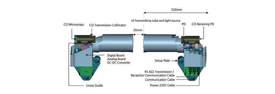
VI/CO measurement meter
The density of the visible distance and carbon monoxide (CO) inside the tunnel is measured to provide the measurement value to the ventilation control system for maintaining the contamination at certain level or below inside the tunnel in a way of providing pleasant tunnel environment and securing the view for safe operation for drivers.
| System configuration |
 |
|
| Major characteristics |
- Holding high precision with the dual optic penetration method
- Long instrumentation distance with expandability
- SW calibration function
- Use of gas shell for calibration for the periodic calibration
- LED ignition to check the arrangement condition
- Available to measure diverse name substance by replacing the luminiscence part
- Effective ventilation system operation by real time data transmitting and storage
- Available to inspect with remote access by the central control device
|
| Specification |
| Category |
Spec |
| Carbon monoxide |
Scope of measurement |
0 ~ 300ppm |
| Accuracy |
± 2ppm |
| Resolving power |
1ppm |
| Visible distance |
Scope of measurement |
0 ~ 15 x 10 / m |
| Accuracy |
± .0.1% |
| Resolving power |
1 x 10 / m |
| Other specifications |
Output conditions |
4 ~ 20mA, RS485 |
| Supplied power |
AC 220 V 60Hz |
| Air-tightness |
IP 65 |
| Installation standard |
Install in a place about 150m from the entry of tunnel pit mouth |
| Install in a place where not influence of jet air stream and natural optics may reach |
| Installation interval 10 ~ 20m |
| Instrumentation indication communication device |
Input signal |
4 ~ 20mA, RS485, DI (4Points) |
| Ooutput signal |
RS-232/422/285 Modbus |
Wind speed meter for Wind direction
| Structure |
 |
|
| Major characteristics |
- Holding high precision with the dual optic penetration method
- Expandable instrumentation distance
- SW calibration function
- Use of gas cell of calibration for periodic calibration
- LED ignition available to check for the arrangement condition
- Available to measure by various pollutant substances with the replacement
- Effective ventilation system operation by the real time data transmitting and storage
- Available to inspect with the remote access by the central control device
|
| Specification |
| Category |
Spec |
| Measurement method |
Ultrasonic transition time |
| Route distance |
Up to 20ml |
| Installation angle |
30 ~ 60º, typical 45º |
| Scope of measurement |
-20 ~ +20 ㎧ |
| Accuracy |
± 2 % of full range |
| Output condition |
4~20mA, optional Modbus |
| Supplied power |
115~230V, 50/60 Hz, 50VA |
| Air-tightness |
IP 65 |
| Installation criteria Measuring range |
The wind velocity is assumed to be the same in all sections of the tunnel
Install around the VICO instrument in the maintenance aspect
Install in the central part and exit part of the tunnel for accurate measurement figure
|
Luminance meter
In order to operate safely by overcoming the inapt phenomenon occurring at this time of automobile operation before and after entering into the tunnel, following the tunnel light standard (KS3703), it is measured for the external brightness and internal brightness to control the panel board to ignite the established light circuit.
- KS 3703 tunnel light standard brightness control
- KS C 7613 brightness measurement method application
- 8-phase light circuit output
- Basic interior for the auto temperature adjuster
| Measurement method |
 |
|
| Major characteristics |
- A total of 4 units for brightness or illumination sensor connection (1 CH, 2 CH, 3 CH and 4 CH)
- Available for monitoring and control in independent maneuvering panel and central control device
- Available for washer/wiper unit option for independent cleansing function
|
| Specification |
| MAYER1600 |
Main controller |
| Classification |
Spec |
| Input |
Brightness and illumination for 4 CH |
| Output |
8-phase optic insulation output |
| Parameter |
Adjustment in accordance with the field condition |
| Monitoring control |
LCD panel of main controller
Central control device |
| Installation location |
Built-in light writch board
Built-in separately independent panel
Built-in RTU panel |
| TS-101 |
Brightness sensor |
| Classification |
Spec |
| Measurement element |
Silicon diode photo cell |
| Scope of measurement |
1∼6,500 cd/㎡ |
| Accuracy |
± 1 % |
| Supplied power |
220V AC or 24V DC |
| Height of installation |
4m |
| Output condition |
4~20mA |
| Special function |
HEATING UNIT (Built-in auto temperature adjuster) |
| Air-tightness |
IP 65 |

 Product
 Tunnel Instrumentation Equipment


